 -
9 minutes read
-
9 minutes read
Understanding Entity-Relationship Diagrams (ERDs) and Their Applications in Database Design

What is an entity-relationship diagram? How do you use it in database design and data modeling? This article will answer those questions.
Entity-relationship diagrams (also known as ER diagrams or ERDs) are potent data model visualization tools used in system analysis and database design to depict the structure and relationships between entities. This article provides a comprehensive overview of ERDs, including their definition, purpose, and practical applications. We will also investigate how dedicated ER diagram tools like Vertabelo can facilitate the creation and administration of ERDs.
Understanding Entity-Relationship Diagrams
An entity-relationship diagram is a graphical representation of entities and their relationships within a system. The ERD functions as a blueprint for database design, enabling stakeholders to comprehend the system's structure, components, and dependencies.
Entities represent objects or concepts within a system. Think of a university system; its entities can include diverse elements like students, courses, professors, and departments.
Each entity's attributes define its properties or characteristics. For example, the attributes of the student entity may include the student's name, ID, date of birth, and email address.
On the other hand, relationships illustrate how entities interact or associate by establishing connections between them. For example, a relationship between the student and course entities may indicate that a student can enroll in multiple courses.
ER diagrams are essential in various stages of system development and database management, such as:
- Collecting requirements: Visualizing entities and relationships aids in gathering system requirements and ensuring comprehensive understanding.
- Communication with business teams: ER diagrams serve as visual communication tools, facilitating the explanation and comprehension of system structures and relationships.
- Database design: ERDs provide a blueprint for the database schema, enabling the effective planning of entities, attributes, and relationships.
- Database debugging: ER diagrams help identify and resolve issues within a database, such as incorrect relationships or missing attributes.
- Database documentation: ERDs document the structure of a database – whether it’s a new one or an existing one. This simplifies future development or analysis tasks.
Types of ER Diagrams
Conceptual, logical, and physical ERD diagrams represent different levels of abstraction in the database design process.
A conceptual diagram focuses on the high-level view of the system and its significant entities and relationships. It does not include any technical implementation details. It provides a broad understanding of the system's requirements and is often used as a communication tool between stakeholders.
A logical diagram takes the conceptual model further by incorporating details like primary keys, foreign keys, and normalization rules. In addition, it defines the database structure without being tied to any specific database management system (DBMS).
Lastly, a physical diagram represents the implementation-specific aspects of the database design. This includes data types, indexing, storage considerations, and optimization techniques. It is closely tied to a specific DBMS and provides the necessary details for database developers and administrators to construct and maintain the physical database.
Notation and Representation in an ERD
When creating entity-relationship diagrams, it is vital to follow notation conventions for consistency and clarity. Some standard notation conventions include:
- Primary Key: In an ERD, the primary key of an entity is underlined. The primary key uniquely identifies each instance of an entity and is crucial for maintaining data integrity.
- Foreign Key: A dashed underline in an ERD denotes a foreign key. It signifies a reference to the primary key of another entity, establishing a relationship between the two entities.
- Crow's Foot Notation: Crow's foot notation is widely used to represent cardinality and modality in entity-relationship diagrams. It utilizes symbols like "1" to indicate one, "M" to describe many, and a crow's foot to signify the "many" end of a relationship. Crow's foot notation provides a clear visual representation of the relationship type between entities.
In database design, relationships between entities are crucial for understanding the structure and interactions within a system. Three common types of relationships are:
- One-to-One (1:1) Relationship: This relationship signifies that each instance of one entity class is linked to just one instance of another entity class. For example, employees may be associated with only one office location in an employee records database.
- One-to-Many (1:N) Relationship: In a one-to-many relationship, an instance of one entity class is connected to multiple instances of another entity class. In a customer and orders database, a single customer can place multiple orders; this establishes a one-to-many relationship.
- Many-to-Many (N:N) Relationship: Many-to-many relationships occur when instances in one entity class are associated with multiple instances in another and vice versa. For example, in a student and course database, a student can enroll in various courses and a course can have multiple students. This results in a many-to-many relationship.
Advanced ERD Concepts
Supertypes and Subtypes
Subtypes and supertypes are sophisticated concepts that model hierarchical relationships between entities in entity-relationship diagrams. Subtypes are specialized entities that inherit properties and relationships from a supertype, which is a public entity. This method permits diverse characteristics and behaviors among affiliated entities. In a vehicle database, the supertype entity could be "Vehicle," while the subtypes could be "Car”, “Truck”, and “Motorcycle”.
By utilizing subtypes and supertypes, designers can capture the nuances and distinctions between related entities while maintaining a cohesive and structured database model. This method increases the flexibility and extensibility of the database design, allowing for future modifications. In addition, subtypes and supertypes generate a more accurate and exhaustive representation of real-world scenarios within the ERD, thereby making the database system more robust and adaptable.
Weak and Strong Entities
In entity-relationship diagrams, weak entities are entities whose existence is contingent upon another entity. Consequently, they cannot be uniquely identified without their parent entity. Strong (or parent) entities, on the other hand, have a unique identifier within themselves and are not dependent on any other entity.
Two rectangles designate weak entities connected to their parents by a double line. In a customer and address database, the "Address" entity may be deemed a weak entity because it depends on the "Customer" entity to establish its identity.
Using weak entities in ERDs enables the modeling of complex relationships in which one entity relies on another. They offer a method to represent entities with a limited existence that require a strong relationship with their parent entity.
By identifying and incorporating vulnerable entities into the entity relationship diagram, designers can accurately depict the dependencies and relationships within the database system, thereby ensuring a comprehensive and cohesive design.
Cardinality and Modality
Cardinality is essential in entity-relationship diagrams because it specifies the numerical constraints on entity relationships. For instance, it sets the minimum and maximum number of participants in a relationship.
In ERDs, cardinality is represented by numbers placed near the relationship lines, allowing for clear comprehension of the constraints and boundaries of the relationship.
Modality, on the other hand, emphasizes an entity’s participation or existence in a relationship. It indicates whether an entity's involvement in a relationship is required (total participation) or voluntary (partial participation).
In ERDs, modality is represented by symbols near the relationship lines, typically "o" for optional participation and "|" for required participation. Modality symbols aid in communicating the requirements and expectations regarding the presence or absence of entities within a relationship, thereby enhancing the clarity and completeness of the ERD representation.
The Importance of ERDs in Software Projects
Entity-relationship diagrams are essential to software projects, as they visually represent the underlying data structure. These diagrams serve as a blueprint for developers, analysts, and stakeholders, facilitating a clear understanding of how different entities within a system relate to one another.
By documenting the relationships and attributes of various entities, ERDs enable effective database design and efficient communication among team members. They serve as a common language, bridging the gap between technical and non-technical individuals involved in the project, fostering collaboration and minimizing misunderstandings.
The clarity offered by ERDs helps ensure that the software project aligns with the desired functionality and meets end users’ needs. Ultimately, a good ER diagram leads to the development of robust and scalable solutions.
Furthermore, ERDs serve as a valuable tool for project planning and management. By visualizing the relationships between entities, ERDs aid in identifying potential bottlenecks or inefficiencies in the data model early in the development process. This allows for timely adjustments and optimizations, reducing the likelihood of costly rework or performance issues.
Likewise, ERDs facilitate the identification of data dependencies and help prioritize development tasks.
Finally, project teams can efficiently allocate resources and schedule tasks by understanding how different entities interact and rely on each other; this ensures a streamlined development process.
ERDs contribute to the overall success of software projects by fostering a structured and well-designed foundation that supports effective data management, system integration, and future scalability.
Using Vertabelo for Entity-Relationship Diagrams
Dedicated data diagraming tools will make it easier to generate accurate and professional ER diagrams. Vertabelo provides various features that facilitate the creation and management of ER diagrams. For example, Vertabelo’s intuitive interface allows you to drag and place entities and relationships onto the diagram canvas. This makes the creation and modification of the ER diagram's structure much faster and easier.
Vertabelo also offers multiple notation options – including Crow's Foot, Chen, and UML – allowing you to select the one that best meets your requirements. This adaptability guarantees that your ER diagram accurately represents the system's relationships and constraints.
Vertabelo provides sophisticated features such as automatic layout adjustment (which assists in organizing and optimizing the visual representation of your ER diagram). A Data Definition Language (DDL) script based on your designed model can be automatically generated. This lets you rapidly convert your ER diagram into SQL statements, saving time and effort during database implementation.
Let’s consider an example from the e-commerce industry. In an e-commerce system, there could be entities for the Customer, Product, and Order. These entities' relationships can be represented using a Vertabelo-created ER diagram.
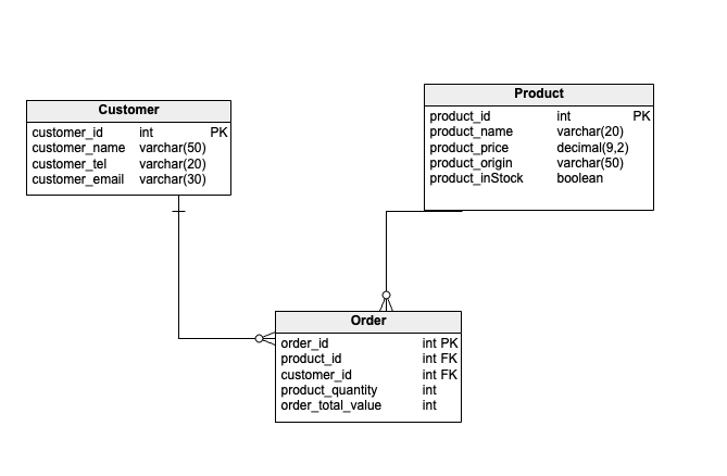
The above ER diagram indicates that a consumer may place multiple orders, that each order may contain multiple products, and that a product may be associated with various orders. Additionally, the diagram depicts the attributes of each entity, such as customer name, order date, and product price.
Vertabelo provides an interactive and collaborative environment that enables multiple team members to work concurrently on the same ER diagram. This feature enhances collaboration and simplifies the design process.
What We’ve Learned About ERDs
Entity-relationship diagrams are indispensable for comprehending system structures, designing databases, and facilitating stakeholder communication. Utilizing specialized ER diagram tools like Vertabelo can help you generate accurate and visually appealing diagrams, simplify database design, and expedite implementation.
ERDs are tremendously important. They can significantly improve your understanding and administration of complex systems, whether you're beginning a new project, documenting an existing database, or debugging an issue.
