

Choosing the right data model pattern is the best way to avoid mistakes and bad decisions when creating a new database schema. To make the right choice, browse through this catalog of current database design patterns and choose the one that best suits your project requirements.
Database design patterns are a useful tool to avoid the task of reinventing the wheel with every new database design you face. Since each design pattern offers proven solutions to common needs, it is just a matter of choosing the right pattern and saving yourself the trouble of starting from scratch.
Of course, with so many database design patterns available, the choice is not trivial. There is no universal pattern that is applicable to all situations. For example, some patterns are geared for high performance in handling queries over large volumes of data. These patterns will be preferable for Business Intelligence databases, for example.
Other patterns are better suited for ensuring data integrity in critical online transactions, such as online banking or airline ticketing systems. Choosing the right pattern will increase your success as a designer, provided you also follow the best practices for database design.
But don’t be afraid of choosing the wrong pattern for your needs. After reading the guide below, you’ll know for sure which design to choose. Once you have chosen your pattern, use a comprehensive database modeling tool like Vertabelo to materialize that pattern.
2024 Catalog of Database Design Patterns
The following catalog brings together the main database schema patterns that will be used in 2024 and beyond. For each pattern, you will learn its benefits, its weaknesses, and when to use it.
All the patterns you will see below are derived from the relational pattern, which is the fundamental model of all relational databases. The relational pattern is commonly represented by entity-relationship diagrams (ERDs). In an ERD, data containers are represented as entities related to each other by matching attributes. A model created with this pattern can easily be converted into a relational database, where each entity becomes a table and each relationship becomes a foreign key or a join table.
For a schema to conform to the relational pattern, it must comply with a number of principles, such as:
- Each entity that makes up the schema must have a unique name.
- Each entity of the schema must be composed of a set of attributes.
- Each attribute of an entity must have a name that’s unique within that entity (i.e., several entities can have an ID field, but each entity can have only one field called ID).
- Each entity must have a primary identifier. Primary identifiers can be one or more rows that have unique values (or combinations of values) in that entity.
- Relationships link pairs of entities, associating attributes of the same type in each of the two related entities.
- When there is a relationship between two entities, the attribute or attributes associated with the relationship in one entity must be the primary identifier of that entity.
Based on the relational pattern, we can derive the following catalog of patterns that cover the most frequent needs of database design.
1. Normalized Form Pattern
This design pattern applies a set of rules that avoid data redundancy and update anomalies in relational schemas. These rules are known as normal forms. There are three main normal forms known as First Normal Form (1NF), Second Normal Form (2NF), and Third Normal Form (3NF).
When you design a database schema by applying the Normalized Form pattern, you basically get the assurance that every piece of data will be stored in one place. And that if you need to change that data, you only need to update it in one place. You can read more about normal forms in the article Normalization in Relational Databases.
Typical Use Case
Common use cases for the Normalized Form pattern involve databases used for transactional systems, where the main requirement is to guarantee the integrity of the information that enters the database in the form of transactions. Transactions are sets of insertion, modification, or deletion operations that are executed on a database in their entirety. That is, all operations are executed in a complete and orderly manner or not executed at all.
How to Implement the Normalized Form Pattern
When designing a database schema for a transactional application, first add all the entities and relationships that compose the schema. Then apply the normalization principles in order. First, verify that the schema complies with the principles of the first normal form. If it does not, make the necessary modifications so that it does. Then the same is done with the principles of the second and third normal forms.
Example of Normalized Form Pattern
The example below demonstrates the Normalized Form pattern. The green schema to the right is the result of applying normalization techniques to the orange (not normalized) table to the left.
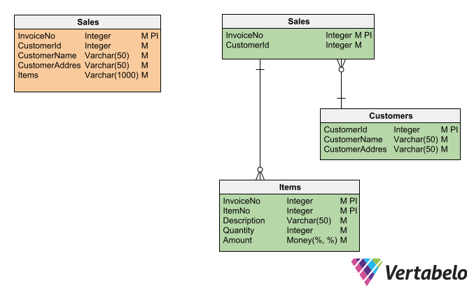
A non-normalized table (left) turns into a subschema of three tables (right) when you transform it using the Normalized Form pattern.
2. Denormalized Form Pattern
Unlike the previous pattern—which seeks to avoid redundancies and anomalies by applying normalization techniques—the Denormalized Form pattern deliberately introduces redundancy into a schema. It does this for several reasons:
- To speed up the performance of certain queries or to simplify their writing.
- To allow historical information to be recorded in a table.
- To store pre-computed values so that they do not need to be recalculated with each query.
The Denormalized Form pattern has some disadvantages that are precisely the inverse of the advantages offered by the Normalized Form pattern. Because of the redundant attributes, more storage space is required. Also, the risk of anomalies is increased: there’s always the possibility of generating different versions of the same data without knowing which is the correct one.
Typical Use Case
The Denormalized Form pattern is mainly used for data warehousing or data analysis, where the priority is to speed up access to data and aggregated information. But it is also applicable to any situation where easy access to historical information or pre-calculated data is required.
How to Implement the Denormalized Form Pattern
If you have two related entities in a Normalized Form pattern, denormalization is implemented by adding to one of the tables’ attributes derived or replicated from the other table; this generates redundancies in the data.
Example of Denormalized Form Pattern
In a schema formed by the Sales and Customers tables, both tables are related by the Client_Id column. In the Sales table, Client_Id is a foreign key that relates to the primary key of the Customers table. To denormalize the Sales table, you’d add the column Customer_Name—even though that information is stored in the Customers table.
This added redundancy will provide two benefits:
- It simplifies and speeds up sales queries where you need to display the customer’s name together with sales data.
- It keeps a record of the name that the customer had at the time of the sale. The customer’s name may vary over time. Therefore, if you add it to the
Salestable, you will have a historical record of the value it had at the time of the sale.
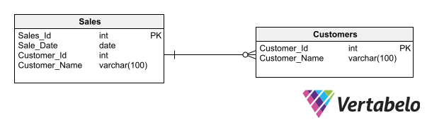
The use of a redundant column (Customer_Name) shows how denormalization could be used to speed up queries and to record historical data.
3. Master-Detail Pattern
The Master-Detail pattern is used in schemas consisting of a parent entity (Master) and a child entity (Detail). For each instance of the Master entity, there is a variable number of instances of the Detail entity.
Typical Use Case
The Master-Detail pattern is commonly used in applications that allow querying or editing detailed data sets of variable cardinality associated with one element in common.
How to Implement the Master-Detail Pattern
To use a Master-Detail pattern in a schema, you need two entities related by a 1:N relationship. The child entity is dependent on the parent entity, which means that the primary identifier of the parent entity is part of the primary identifier of the child entity.
Example of Master-Detail Pattern
ERP (Enterprise Resource Planning) applications that manage customer lists typically use the Master-Detail pattern to store branch details for each customer. The attributes of the parent entity (Customer) usually include Customer_Id (primary identifier), Customer_Name, Tax_Id, and so on. The child entity (Branch) is identified by Customer_Id (a foreign key to the parent entity) and Branch_No; its attributes include Address, Telephone, etc.
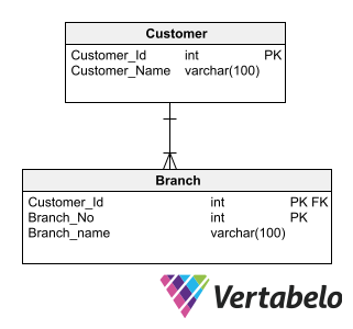
A data model composed of the tables Customer and Branch. Each customer could have an arbitrary number of branches, making this a typical use case for the Master-Detail database design pattern.
The applications that employ a data model based on the Master-Detail pattern usually let users navigate through the instances of the master entity and, when needed, expand a list of the related instances of the Detail entity.
4. Entity-Attribute-Value (EAV) Pattern
Relational schemas have the disadvantage that the tables where data reside have a rigid structure: All data elements in a table must have exactly the same attributes. If the need arises to store a new attribute in a table, the structure of the whole table must be modified, affecting all the rows in it. And this can mean the need to restructure millions of rows of data.
One way to give more flexibility to the traditional relational model is to apply the Entity-Attribute-Value pattern. This pattern provides a way to store entities with a variable number of attributes in a more flexible and extensible way.
Typical Use Case
The EAV pattern is commonly used in situations where the number of attributes can vary for each instance of an entity or where the number of attributes is unknown in advance. It is also used where extensibility is required to add new attributes dynamically or when instances of an entity have disparate subsets of attributes.
How to Implement the EAV Pattern
According to the EAV pattern, each entity in the data model requires its data to be stored in (at least) three tables:
- Entity table: This table represents the primary entity being modeled. It should contain a primary key column to uniquely identify each instance of the entity.
- Attribute table: This table stores the attributes or properties associated with the main entity. It includes meta-attributes such as
Attribute_Id,Attribute_Name,Data_Type, and any additional metadata. - Value table: The value table stores the actual values of the attributes of each entity. It typically includes columns for the entity ID, the attribute ID, and the corresponding attribute value.
Example of EAV Pattern
Companies that manufacture home appliances have a catalog of products with very disparate characteristics. It is common for the products in each catalog line to have a different set of attributes. Within the Vacuum Cleaner line, for example, the attributes may be suction power and capacity; in the Oven line, they may be type of cooking, temperature range, etc.
To model such a situation using an EAV pattern, you need to create a Product entity, an Attribute entity, and an Attribute_Value entity containing the attribute values for each product. The Value attribute in the Attribute_Value entity must be of the most comprehensive data type possible (in this example, Varchar(8000)), since it is not known in advance what values it will have to store.
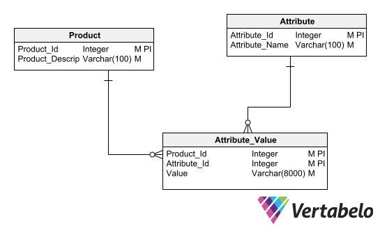
The Entity-Attribute-Value design pattern requires three tables to model entities with variable sets of attributes.
5. Ternary Relationship Pattern
In entity-relationship models, there can be relationships between three or more entities; these are generically called n-ary relationships. They are not very common, but they do exist. And the most convenient way to model them is with a Ternary Relationship pattern.
Typical Use Case
Any situation in which you must form sets by taking elements from three different and independent sources is suitable to be modeled with a Ternary Relationship pattern.
It is important to note that the three entities must be independent. If there is a dependency between two of the entities, the situation could be better modeled using the Master-Detail pattern we saw above.
How to Implement a Ternary Relationship Pattern
When creating the conceptual model, you can use Chen’s notation to represent a ternary relationship. Just place a rhombus (a symbol that in Chen’s notation represents a relationship) linked to three entities.
When taking the model to the logical level (and later to the physical level), you will lose the possibility of representing a relationship involving three entities. Therefore, you need to turn the rhombus that represents the ternary relationship into a new entity. This new entity must be associated (through binary relationships) with the three entities involved in the relationship.
Ternary Pattern Example
A model for an educational institution involving the independent entities Teacher, Course, and Student is an ideal situation to apply the ternary relationship pattern. You need a fourth entity to connect the three entities. This fourth entity can be called Class, which sounds pretty straightforward since a class associates a teacher with a subject and one or more students.
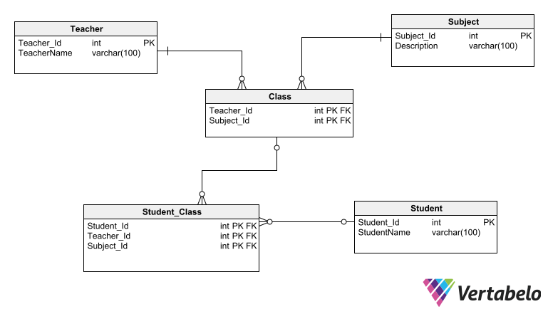
In this example, the Ternary Relationship Pattern uses intermediate tables to relate the three related entities Teacher, Student, and Subject.
6. Star Pattern
The Star pattern is fundamental to creating a schema for data warehousing. It is called Star because at its center is a fact table. The fact table is related to several dimension tables surrounding it, acquiring a shape that—seen from afar—could resemble a star.
The Star schema model is characterized by its simplicity. It is easy to maintain and understand; just looking at the ERD, you can realize its structure and the way it should be used.
Typical Use Case
The Star pattern is used to create basic data models for data warehousing. These consist of a single fact table and n simple dimension tables, which are related to the central fact table.
How to Implement the Star Pattern
Start with a blank ERD and place a fact table in its center. Then, add the dimension tables surrounding the fact table. The dimension tables have a simple primary key (normally a surrogate ID column) that relates them to the foreign keys located in the central fact table.
Star Pattern Example
The Star pattern is commonly used to create analytical sales databases. The central fact table stores cumulative sales information according to a set of attributes.
Along with the aggregated sales information, the fact table stores foreign keys that point to the dimension tables surrounding it—e.g., year/month, region, product family, sales channel, etc.
Related dimension tables have a simple primary key, a description, and any other relevant data associated with the dimension.
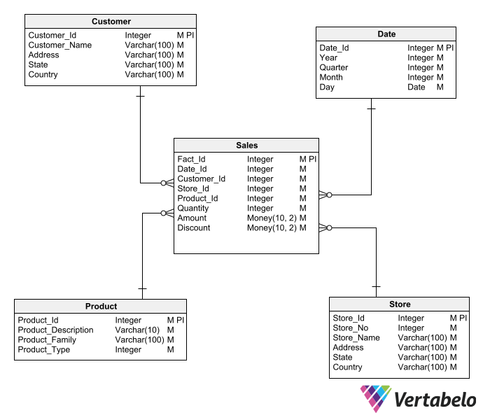
A simple dimensional schema using the basic Star pattern.
7. Snowflake Pattern
This design pattern is called a Snowflake because of the way the dimension tables branch out from a central fact table. These ramifications make diagrams following this pattern resemble (with a little bit of imagination) the fractal shape of snowflakes.
The basic idea behind any schema that follows the Snowflake pattern is that the dimension tables are normalized. This means that each dimension is not contained in a single table, but that there is a “parent” dimension table that has several lookup tables describing it. In turn, these lookup tables can branch into other lookup tables, so that each dimension is expressed by a fully normalized subschema.
Typical Use Case
The snowflake pattern is applicable to data warehousing models where the dimensions describing the fact table present a complex structure that cannot be expressed by a single table. This could be the case of a Location dimension, which contains the name of a neighborhood that belongs to a city, then a county, a state, and a country.
How to Implement the Snowflake Pattern
To implement a Snowflake pattern, you must apply normalization techniques (as we saw with the Normalized Form pattern above) to each of the dimensions surrounding the fact table.
If a dimension can be represented by a single table, nothing needs to be done. Otherwise, that dimension should be considered as a subschema that must be taken to 3NF, generating as many lookup tables associated with the dimension’s main table as necessary.
Snowflake Pattern Example
The dimension tables in the Star pattern example from above are clearly not normalized. If you work with the data model to get it into 3NF, you could have an ERD more or less like this:
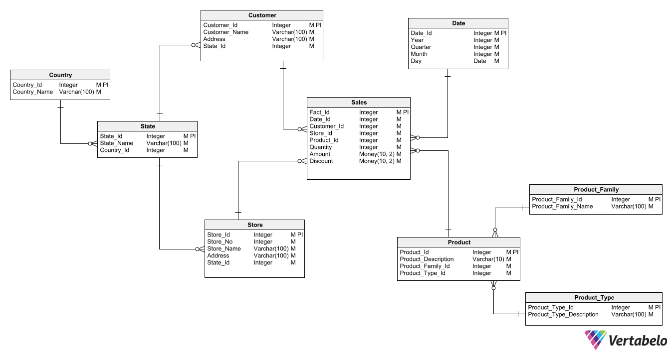
A central fact table is surrounded by sub-schemas for each related dimension.
Note that some of the single-dimension tables that surrounded the central fact table in the previous Star pattern were decomposed into normalized sub-schemas to adapt the model to the Snowflake pattern.
8. Galaxy (a.k.a. Constellation) Pattern
The Galaxy pattern—also called the Constellation pattern—is an extension of the Star and Snowflake schemas. In a Galaxy pattern, multiple Star or Snowflake schemas are created to handle different business areas in a single data model.
The advantage of the Galaxy pattern is that it allows modeling complex data warehousing schemas in which multiple fact tables coexist. For example, this might occur when you need to gather information coming from different business areas.
The Galaxy pattern also has the advantage of sharing dimension tables between the different fact tables.
Typical Use Case
Galaxy patterns are appropriate in situations where data from different business areas should be kept together in a single data warehouse. The main reason for doing so is to support reports that establish correlations between unrelated data from disparate sources.
Another area of application of the Galaxy pattern is when you need to unify the resources required by a data warehouse: storage, processing, maintenance tasks, etc. This avoids the necessity to escalate resource consumption when adding a new business area.
How to Implement the Galaxy Pattern
The implementation of a data warehouse that follows the Galaxy pattern generally starts from an existing Star or Snowflake schema. This schema adopts a Galaxy pattern the moment you add a second fact table. This second fact table is also implemented following a Star or Snowflake pattern (as appropriate). However, you recognize that some dimension tables may already exist in the schema and do not need to be recreated. You just need to link them to the new fact table by adding a foreign key to it.
Galaxy Pattern Example
In this example diagram below, you can see two fact tables: SalesFact and ProcurementFact. These two tables share the following dimension tables: Product and Time. There are other dimensions that are unique to one of the fact tables: Client and SalesPerson are related to SalesFact, and Provider and BuyerAgent are related to ProcurementFact.
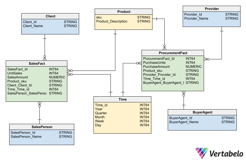
The two fact tables in this Galaxy pattern share two dimension tables, which helps save server resources.
Database Design Patterns for a Whole Year
The data model patterns we’ve presented in this article will give you a head start whenever you have to create a new database design in 2024. If new use cases arise for which you have no suitable database design patterns, rest assured that they will be covered on these pages.
