

This article will guide you through the necessary steps to create a database model for a banking system. We’ll use the Vertabelo online data modeler to define all the required entities and the relationships between them.
Bank legislation varies from country to country, and not all banks offer the same products and services. In this article, we’re going to create a generic ER diagram for a banking system. This database design may require adjustments or modifications based on your own requirements and your local legal and industry regulations.
Creating a Banking Data Model Using Vertabelo
Vertabelo is a powerful web-based tool that allows us to create logical and physical data models. We can also use it to automatically generate SQL scripts so we can deploy the model tables in a physical database. If you want to learn more about the differences between logical and physical models, you can read What Are Conceptual, Logical, and Physical Data Models?.
Creating a Logical Data Model
Let’s begin by creating a logical data model that can be later used to create both a physical model and the SQL scripts to implement it. (We won’t go into the process of generating the physical model from the logical model and then generating code from the physical model to implement the database, but we’ll include links to other articles on those topics.)
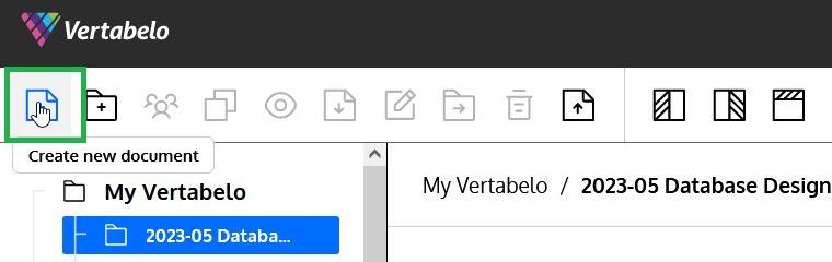
The first step to create a model in Vertabelo is to click the Create New Document button on the menu bar:
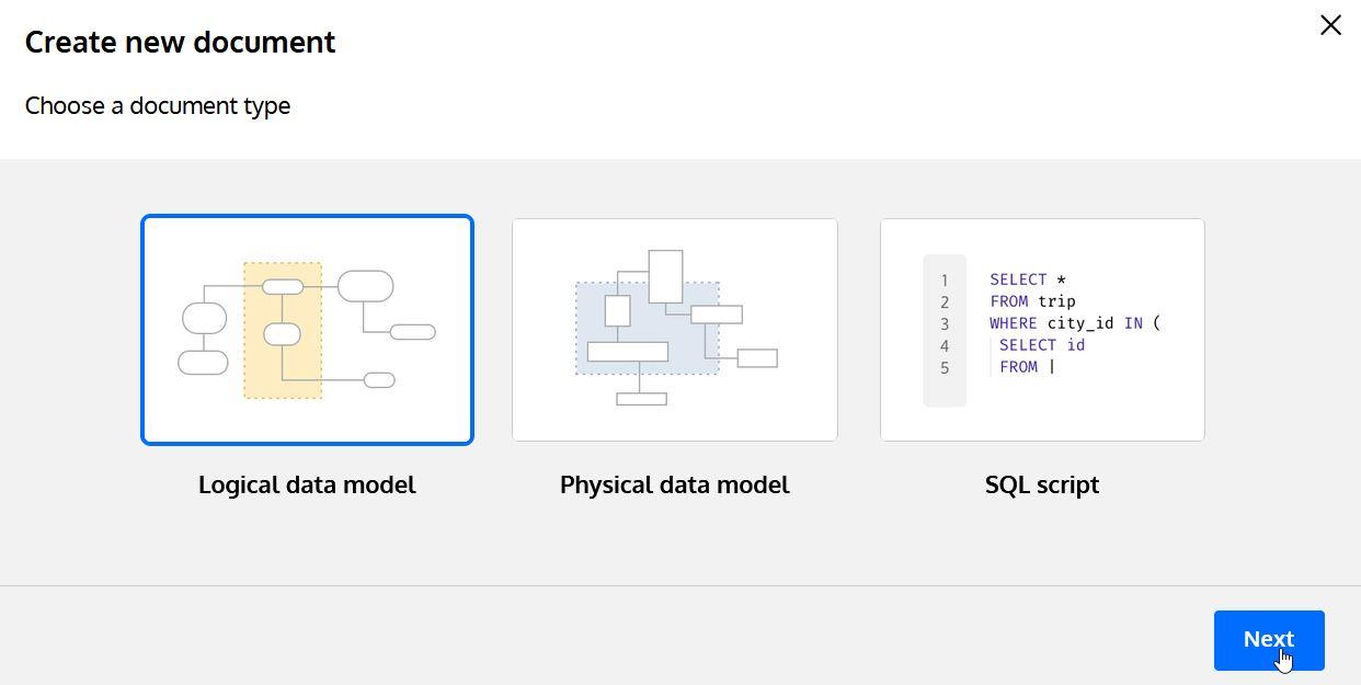
Then, select the document type (here, “Logical Data Model”) and press Next:
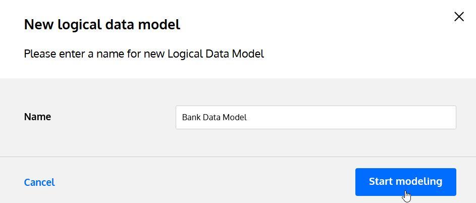
The last step before we start modeling is to provide a name for the data model:
Now we have an empty model. We’re ready to start designing our entities. If you’re new to database design, you may want to read Data Modeling Basics in 10 Minutes to familiarize yourself with the basic concepts.
Creating Entities in a Logical Data Model
Once we have a model, we need to start adding the entities that will be part of the system we are designing. We can do this by selecting the Add New Entity button on the diagram taskbar, as shown below:
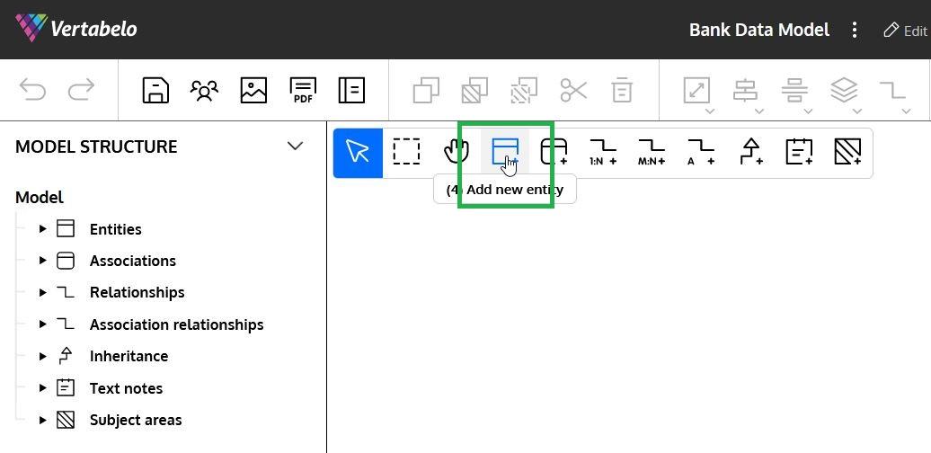
After that, we can click on any empty space of the diagram and the new entity will be created.
Let’s review the different entities and learn how to create them in our model.
Person
This entity will keep information about each person that interacts with the bank, either as a customer, an employee, or any other role.
Note: A Person can be an individual or an organization.
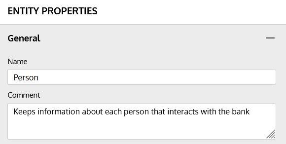
General Information
The first thing we need to do is provide the desired entity name and a note about this entity. We can do this using the first section of the Property Panel, which is situated to the right of the diagram:
Attributes
We are going to define the following attributes for the Person entity:
PersonID: This will be a unique ID number and primary identifier (later the surrogate primary key) of the entity. We will use an INTEGERLastName: The person’s surname. We will use a VARCHAR(100) datatype.FirstName: The person’s first n We will use a VARCHAR(100) datatype.DateOfBirth: The person’s birth date We will use a DATEEmail: Their email a We will use a VARCHAR(100) datatype.PhoneNumber: Their phone n We will use a VARCHAR(20) datatype.Address: The person’s mailing address. Usually, you would store this information as separate attributes and entities (like Street, Street Number, City, State or Country). For simplicity’s sake, we’ll group it together here. We will use a VARCHAR(100) datatype.TaxIdentifier: This number or code is used to uniquely identify the person or organization for tax purposes (like SSNs or TINs in the US). We will use a VARCHAR(20) datatype. We will use this attribute as an additional Identifier for the entity.
We can define all the attributes for this entity the Entity Properties panel:
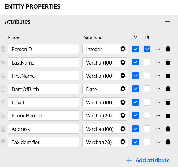
Note #1: the “M” toggle box indicates if the attribute is mandatory. The “PI” toggle box indicates if this attribute is part of the primary identifier (primary key) of the entity.
Note #2: Clicking on the gearbox symbol next to each attribute opens a wizard that simplifies picking the correct data type.
Note #3: All attributes mentioned in this article will be mandatory unless explicitly identified as optional or nullable.
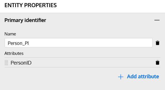
Primary Identifier
Although we have already selected the PersonID attribute as the PI in the Attributes section, we can define a name for the primary identifier. We can also modify the attributes that are part of it in the following section of the Entity Properties panel:
The primary identifier will be converted in the physical model into a primary key (PK). The article What Is a Primary Key? will help you understand the importance of keys in a database model.
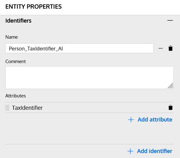
Additional Identifiers
Besides the surrogate primary key that we have defined for the entity, we can also create additional identifiers (natural keys) that help uniquely identify each row. In this example, we are going to use TaxIdentifier as an additional identifier in the next section of the Entity Properties panel:
Now the first of our entities is complete and we know how to create entities and their attributes in the logical model. Let’s review the other entities we are going to include in our system.
Branch
This entity will keep basic information about the different branches or offices of the bank. It will have the following attributes:
BranchID: A unique identification number and the surrogate primary key of the table. INTEGERBranchName: The commercial name of the branch or office and an additional identifier. (There cannot be two branches with the same name.) VARCHAR(100) datatype.BranchCode: An internal code used to identify the branch in account numbers. This is also an additional identifier, as there cannot be two branches with the same code) and additional identifier (there cannot be two branches with the same code). VARCHAR(10) datatype.Address: The physical address of this branch. As with the Person entity, we are not normalizing this information for simplicity’s sake. VARCHAR(100) datatype.PhoneNumber: The branch phone number. VARCHAR(20) datatype.
Employee
This entity will store information about the persons that are also bank employees. Besides having all attributes of a Person, they will have these additional attributes:
EmployeeID: A unique ID number and the surrogate primary key of the table. INTEGERPosition: Describes the position of the employee. VARCHAR(20) d
Note #1: Each employee is related to a Person and to a Branch. We will see how to create those relationships later in this article.
Note #2: Positions could (and should) be normalized in a separate entity. To keep the model simple, we are using a denormalized version.
Customer
This entity will store information about the persons that are also bank customers. Besides having all attributes of a Person, they will have these additional attributes:
CustomerID: A unique identification number and the surrogate primary key of the table. INTEGERCustomerType: Categorizes the client based on bank policies (g. regular, premium, etc.). VARCHAR(20) datatype.
Note #1: Each employee is related to a Person. We will see how to create those relationships later in this article.
Note #2: Customer type could (and should) be normalized in a separate entity. To keep the model simple, we are using a denormalized version.
Account
This entity keeps information about the different accounts each customer or group of customers can have in the bank. It has the following attributes:
AccountID: The surrogate primary key of the table. INTEGERAccountType: Defines the account type (e.g. savings, checking, credit, etc.) and serves as part of the entity’s unique identifier. VARCHAR(20) datatype.AccountNumber: Together with AccountType, this uniquely identifies the account in the bank. It usually includes the branch code. VARCHAR(20) datatype.CurrentBalance: The current balance available on the account. DECIMAL(10, 2) datatype.DateOpened: Date the account was opened. DATEDateClosed: Date the account was closed. DATE datatype and not mandatory.AccountStatus: Defines if the account is active, suspended, closed, etc. VARCHAR(20) datatype.
Note #1: Each account is related to one or more Customer and to a Branch. We will see how to create those relationships later in this article.
Note #2: Both account type and status could (and should) be normalized in separate entities. To keep the model simple, we are using a denormalized version.
Loan
This entity keeps information about the different loans that the bank grants to customers. We are going to create it with the following attributes:
LoanID: The surrogate primary key of the table. INTEGERLoanType: Defines the type of loan granted to the customer (e.g. personal, mortgage, auto). VARCHAR(20) datatype.LoanAmount: Total amount of the loan. DECIMAL(10, 2) datatype.InterestRate: The yearly interest rate used to calculate interest. DECIMAL(10, 2) datatype.Term: Duration (in months) of the loan. INTEGERStartDate: The date the loan becomes DATE datatype.EndDate: The date the loan should be completely paid. DATEStatus: Defines if the loan is active, canceled, closed, etc. VARCHAR(20) datatype.
Note #1: Each loan is related to one Customer. We will see how to create those relationships later in this article.
Note #2: Both loan type and status could (and should) be normalized in separate entities. To keep the model simple, we are using a denormalized version.
Loan Payment
Loans usually have a scheduled number of payments that include both principal and interest. The LoanPayment entity in our model represents these scheduled payments. It has the following attributes:
LoanPaymentID: The surrogate primary key of the table. INTEGERScheduledPaymentDate: The pre-scheduled date of each payment. DATEPaymentAmount: The expected total amount to be paid on the scheduled date. DECIMAL(10, 2) datatype.PrincipalAmount: The expected principal amount to be paid on the scheduled date. DECIMAL(10, 2) datatype.InterestAmount: The expected interest amount to be paid on the scheduled date. DECIMAL(10, 2) datatype.PaidAmount: The actual amount paid. DECIMAL(10, 2) datatype.PaidDate: The actual date when the payment was completed. DATE datatype and not mandatory.
Note #1: Each loan payment is related to one and only one Loan and can be paid in one or multiple Transactions. We will see how to create those relationships later.
Transaction
Each operation performed in a bank is usually represented by one transaction (e.g. deposit, withdrawal) or multiple transactions (e.g. account transfers). The Transaction entity in our model will handle those operations. It has the following attributes:
TransactionID: The surrogate primary key of the table. INTEGERTransactionType: Defines the type of transaction performed (e.g. deposit, withdrawal, transfer). VARCHAR(20) datatype.Amount: The amount involved in the operation. DECIMAL(10, 2) datatype.TransactionDate: The date and time the transaction was performed. DATETIME
Note #1: Each transaction is related to one Account and can be related to another Transaction (for example, when a transfer between two accounts is performed). It can also be related to an Employee if it was performed manually in an office/branch. And as we mentioned before, it can also be related to a LoanPayment. We will see how to create those relationships later in this article.
Note #2: Transaction types could (and should) be normalized in a separate entity. To keep the model simple, we are using a denormalized version.
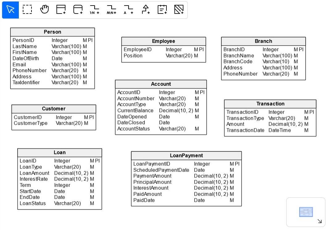
After creating all the entities, we will have a data model with no relationships established:
Creating Relationships Between Entities
Once we’ve defined all of our entities, we need to establish the relationships between them. Depending on the type of relationship (one to many or many to many) we will use one of the following buttons on the diagram taskbar:

Let’s analyze the relationships in our model.
Person – Customer
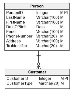
Each Customer in our model is a single Person, but not all persons are customers. We need to establish a 1:N (one-to-many) relationship between the two tables, N being either 0 or 1.
We need to select the Add 1:N Relationship button, click on the Person entity, and – keeping the mouse button pressed – move the mouse over the Customer entity and release the button. We should see that a line between the two entities has been included in the diagram:
Now we need to define some additional features of the relationship. We’ll edit the properties using the Relationship Properties panel on the right side of the diagram; click on the relationship line to access it.
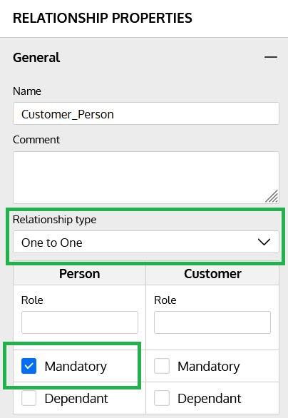
In this case, we have changed the relationship type to “One to One” and indicated that the Person is mandatory in the relationship, meaning that each Customer must be related to a Person.
Person – Employee
Each Employee in our model is a single Person, but not all persons are employees. Once again, we need to establish a 1:N relationship between the two tables, N being either 0 or 1.
Branch – Employee
All employees work at a branch of the bank, and every branch can have many employees, so we need to create a 1:N relationship between the Branch and Employee entities.
Customer – Account
A customer can usually have multiple accounts; depending on legislation and regulations, most systems allow shared accounts between multiple individual customers (family members, etc.). To represent this in our system, we are going to create a many-to-one (M:N) relationship between Customer and Account.
After creating the relationship, we need to verify that the relationship is mandatory on the customer side. There can be customers without any account, but each account must be related to at least one customer.
Branch – Account
This is a 1:N relationship, since a single branch can have multiple accounts and each account must belong to one and only one branch.
Customer – Loan
This is usually a 1:N relationship, since loans are granted to a single customer but a customer can have multiple loans.
Loan – LoanPayment
This is also a 1:N relationship. We need to ensure that both sides are mandatory, since each payment must belong to a loan and each loan must have at least one scheduled payment.
LoanPayment – Transaction
A loan payment is usually paid in a single operation, but most banking systems will allow for partial payments. This means that we need to create a 1:N relationship between the Payment and Transaction entities but with both sides being non-mandatory.
Account – Transaction
This is also a 1:N relationship, since transactions involve a single account and accounts can have multiple transactions.
Employee – Transaction
Most transactions are performed directly by users via banking apps, online banking, or ATMs. However, there are still some operations that can be made at a bank office and involve an employee. To support this, we need to establish a 1:N relationship between the Employee and Transaction entities and ensure that none of the sides are mandatory.
Transaction – Transaction
There are several scenarios where a transaction needs to be related to another transaction in the system. Some of them are:
- Transfers between two accounts. The transaction that “adds” money to the target account should be related to the one that “subtracts” money from the source account.
- Adjustments made to a charge should be related to the actual transaction that was later adjusted.
In this case, we need to create a 1:N relationship to the same Transaction entity. We achieve this by selecting the 1:N button and just clicking on the desired entity. We also need to ensure that both sides of the relationship are not mandatory.
The Final Banking System Logical Model
Let’s look at our complete logical diagram of a generic banking system:
Database Design Next Steps
The next step – after checking and validating the banking database model you currently have – is to transform it to a physical model, which includes database-specific information. After that, you can use Vertabelo to automatically generate the DDL script to build the database. As promised, here are some resources to walk you through these processes:
- How to Generate a Physical Diagram from a Logical Diagram in Vertabelo
- How to Generate a SQL DDL Script in Vertabelo
And if you are curious about other business-specific data models, check out the other example ER diagram articles in this blog!
