

Read this article to find out how to create an ER diagram for hospital management systems.
Commonly, we start the database creation process by designing a logical database diagram. This diagram is a visual representation of the entities in a system and the relationships between them. Later in the process, the logical diagram is transformed into a physical database diagram that incorporates database-specific details.
In this article, we’ll walk you through building an entity-relationship diagram (ER diagram or ERD) for a hospital management system. First, we’ll introduce ER diagrams and the general rules for database modeling. Next, we’ll create the database model using the Vertabelo data modeler. This process consists of the following steps:
- We begin by designing a logical database model of entities with attributes and relationships between them.
- We use the logical database model designed in the first step to generate a physical database model for a specific database engine.
- Finally, we generate an SQL DDL (Data Definition Language) script to create a database based on the designed model.
Let’s get started.
Before We Start Modeling
What is an ER Diagram?
An ER diagram is a database model that illustrates entities (such as objects, people, or concepts) with their attributes (such as name, type, or age). Entities can be linked with one another; the nature of these links, or relationships, depends on how entities interact.
Here is a simple example of an ER diagram:
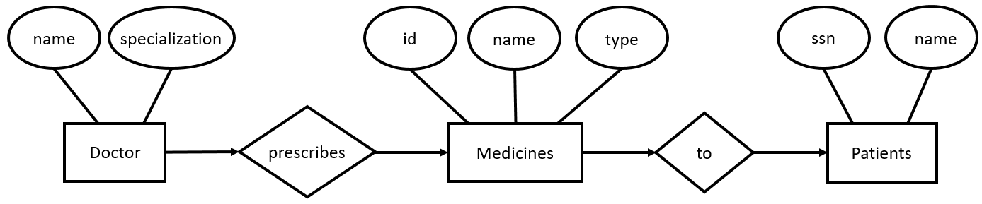
Let’s analyze it briefly. We’ve got three entities:
- The Doctor entity has the following attributes: name and specialization.
- The Medicines entity has the following attributes: id, name, and type.
- The Patients entity has the following attributes: ssn and name.
The relationships between the entities indicate that a Doctor prescribes Medicines to Patients.
This ER diagram presents a real-world scenario where a doctor of a particular specialization prescribes certain medicines to a patient.
There are different types of ER diagrams. The most widely used are conceptual, logical, and physical database models, which add some abstraction layers on top of the ER diagram presented above.
Database Modeling Process and Rules
The process of database modeling involves people from different domains – such as database designers, data modelers, business stakeholders, and potential system users.
The first step in the process is to define data requirements using the conceptual database model, which is database independent. The conceptual model is very high-level and is the model shared with business (i.e. non-technical) stakeholders.
Next, we translate the conceptual model into the logical database model. This model details the structure of the data. Finally, the logical database model is transformed into the physical database model that outlines the tables’ structure and considers performance and storage details for a specific database engine.
Let’s go over some essential rules for database modeling:
To enforce data integrity, each table must have a primary key that uniquely identifies each row. Here are the reasons why a primary key is so important.
Example: Each patient is identified uniquely by their social security number (SSN).
To satisfy the first normal form (1NF), column values must be atomic – that is, each column must hold a value (like first name or ID number) that cannot logically be broken down into more values.
Example: The type of medicine may fall into one or more of the following categories: homeopathy, allopathy, tablets, capsules, injections, etc. Instead of listing all values in one column, we create a new table that assigns each medicine to its categories as follows:
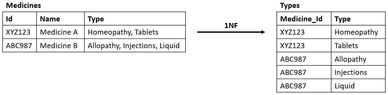
The Type column now refers to the Types table. This table stores all the different types of medicine, linking to the Medicines table via a foreign key.
- To satisfy the second normal form (2NF), there should be no partial dependencies in the tables – that is, all columns should be dependent on the entire primary key. You can learn more about database normalization here.
- To satisfy the third normal form (3NF), all transitive functional dependencies must be removed.
These are the most basic data modeling rules; you can check out our article on data modeling basics or view the database modeling topic on our blog to learn more.
Let’s Create an ER Diagram for Hospital Management System
Now that we’ve gone through the core principles of data modeling, let’s begin on our hospital management system ERD. We’ll start by creating a logical database model.
Logical Database Model
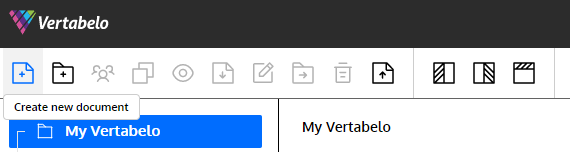
Here is how to create a logical data model in Vertabelo:
- Click on the Create new document button.
- Choose the Logical data model and click on the Next
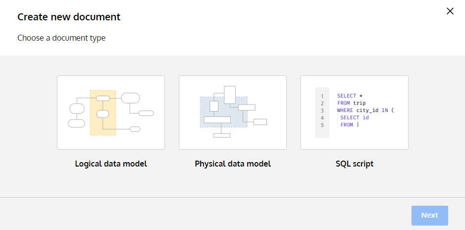
- Name your model and click on the Start modeling
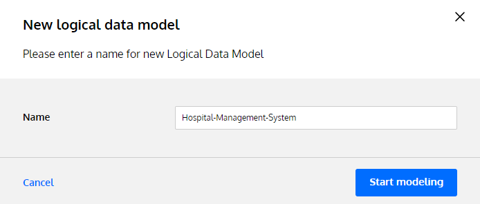
Now you’re ready to start modeling.
Let’s first identify all relevant entities:
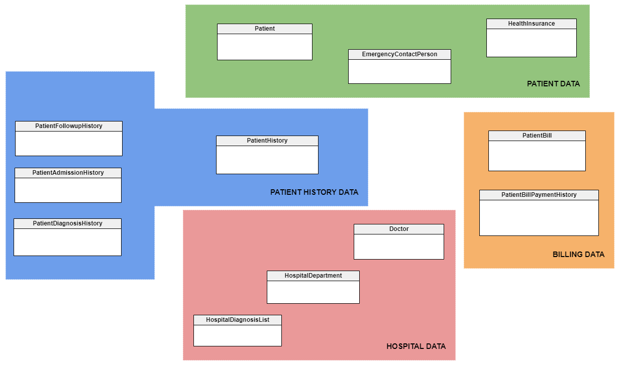
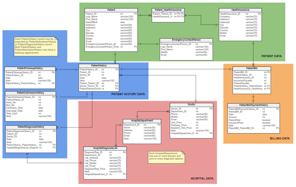
You’ll notice that we’ve also defined subject areas (PATIENT HISTORY DATA, HOSPITAL DATA, etc.) in various colors. Subject areas are a convenient way to see which tables share related data. You can add both subject areas and text notes from the left pane menu. To improve the readability of your database model, we encourage you to use subject areas and text notes.
You can create entities in Vertabelo by selecting the Add new entity button.
Patientstores all patients’ data.EmergencyContactPersonstores emergency contact person details. Each patient has one emergency contact person.HealthInsurancestores health insurance providers’ data. Each patient may have one or more health insurance providers.HospitalDepartmentstores all hospital departments’ details.Doctorstores all doctors’ data, including different visit prices. Each doctor belongs to one department.PatientHistorystores the history of any interaction between a patient and a doctor. It may be extended byPatientAdmissionHistory(if a patient is admitted to the hospital),PatientFollowupHistory(if there is a follow-up appointment), orPatientDiagnosisHistory(if there is a diagnostic test performed).PatientAdmissionHistorystores the hospital admission history data of each patient. It links to aPatientHistoryrecord.PatientFollowupHistorystores follow-up appointment history data. It links to aPatientHistoryrecord.PatientDiagnosisHistorystores the history of patients’ diagnostic test results. It links to aPatientHistoryrecord.HospitalDiagnosisListstores the list of diagnosis tests offered by a hospital. It links to aPatientDiagnosisHistoryrecord. It also links to theHospitalDepartmentthat performed the test.PatientBillstores billing data based onPatientHistoryrecords.PatientBillPaymentHistorystores payment data based onPatientBillrecords.
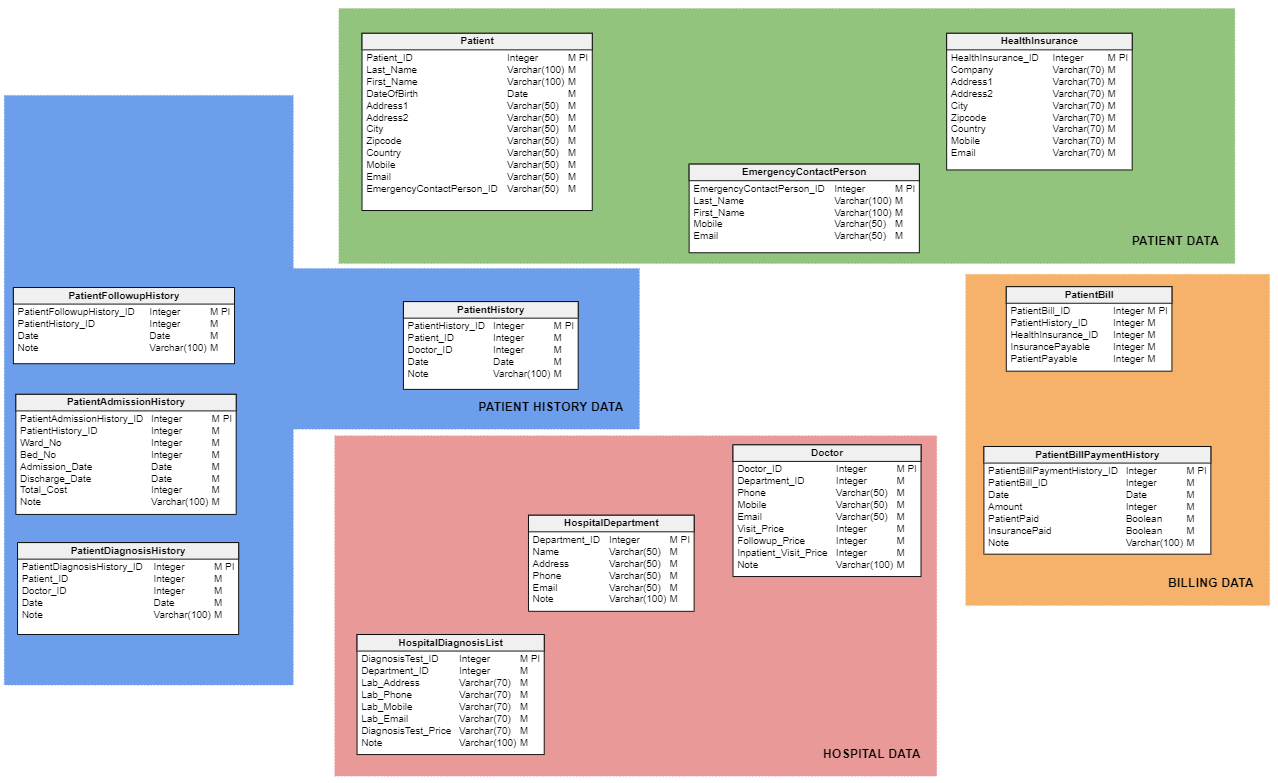
Next, we assign attributes to each of the entities. Attributes describe details or traits for each entity. For example, the Patient table includes attributes for a patient ID number that’s unique to each patient, the patient’s first and last names, their address, date of birth, and so on.
You can assign attributes to entities in Vertabelo by selecting an entity and clicking on the Add attribute button in the right pane.
Finally, we define the relationships between the entities, including cardinalities. Here is the resulting logical data model:
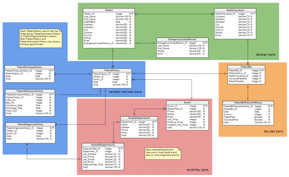
Let’s analyze the cardinalities:
- Patient data:
- Each patient has one or more health insurance providers.
- Each health insurance provider has zero or more patients.
- Each patient has one emergency contact.
- Patient history data:
- Each patient has one or more patient history/visit records.
- Each patient history/visit record has zero or more follow-up history/visit records.
- Each patient history/visit record has zero or one hospital admission records.
- Each patient history/visit record has zero or more diagnosis records.
- Hospital data:
- Each doctor has one or more patient history/visit records.
- Each doctor is assigned to one department.
- Each department has one or more doctors.
- Each department offers zero or more diagnosis tests.
- Billing data:
- Each patient history/visit record has one patient bill record.
- Each patient bill record has one payment record.
Now that the logical data model is completed, let’s generate the physical data model.
Physical Database Model
Let’s use Vertabelo to convert the logical database model into the physical database model. Here are 8 things to consider when creating a physical data model.
You can generate a physical data model from a logical data model with just a few steps in Vertabelo:
- In the logical data model, click on the Generate physical model Alternatively, you can use Ctrl + G on your keyboard.

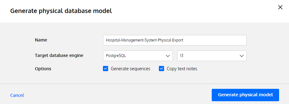
- Name your physical model and choose the database Then click on the Generate physical model button.
Here comes the physical data model:
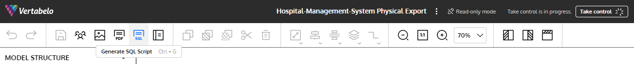
Please note that the generated physical data model comes in a read-only mode by default. To make it editable, click on the Take control button on the top.
As you may notice, the many-to-many relationship between the Patient table and the HealthInsurance table is now implemented via the Patient_HealthInsurance table. Also, the data types are adjusted to the chosen database engine (here, PostgreSQL) – for example, an Integer is now an int. Furthermore, the foreign key constraints are marked in the model.
Bring your Database Model to Life
Another handy Vertabelo feature is automatically generating an SQL DDL script for the database model. This script will allow you to import your script and build your physical database. Here is how to do that:
- In the physical data model, click the Generate SQL Script Alternatively, you can use Ctrl + G on your keyboard.
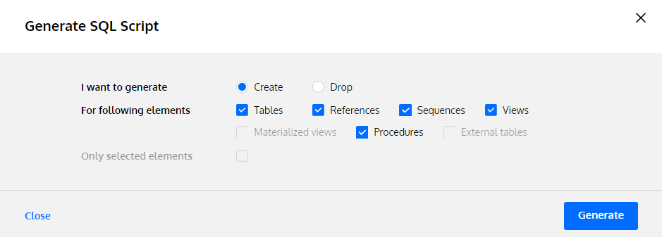
- Select the type of script you want to generate (either Create or Drop) and the elements to be included. Then, click the Generate
- Name the file and choose whether to save it in Vertabelo Cloud storage or download it.
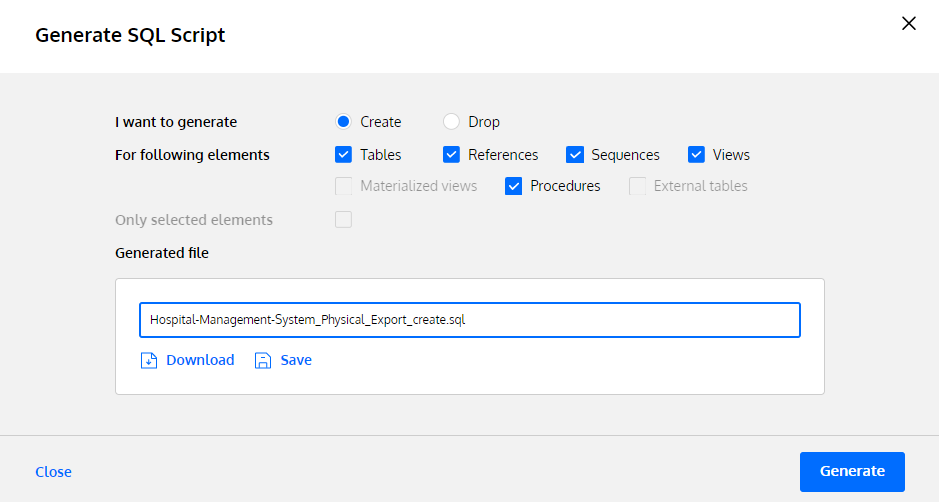
- Click the Close button to close the window.
Now you can import this SQL DDL script to create a database. As we created the physical data model for the PostgreSQL database engine, we can import our SQL DDL script into pgAdmin:
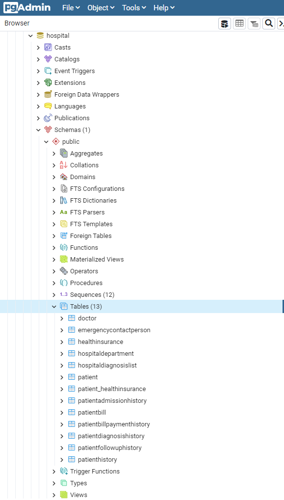
Once that’s done, you’re ready to insert your data.
You’ve Created a Hospital Management Data Model. What’s Next?
It is very easy to create your own database with the help of Vertabelo.
You start with an idea of what entities should be included. Then you assign attributes to all entities and define the relationships between them. That’s how you get to the logical data model.
Vertabelo creates a physical data model for you. Furthermore, it can develop an SQL DDL script that can be executed to create your database.
Make sure to try it out yourself.
Good luck!
