

Learn how to create a database diagram using a data modeling tool for SQL Server.
Microsoft SQL Server is one of the most popular database management systems (DBMS) among database developers. It’s used by many large organizations for a variety of databases. So, it is worth learning how to create a database diagram in SQL Server.
A perfect database starts with a great database model. If the database is a skyscraper, the data model is the foundation. Thus, choosing a good SQL data modeler is crucial in your database creation process. I use the Vertabelo online data modeling tool for SQL Server.
Let’s create a SQL Server database diagram using the Vertabelo online database diagram tool. We will create a data model for an online shopping app. But first, let’s quickly review the types of data models available.
Conceptual, Logical, and Physical Diagrams
There are three types of data models: conceptual, logical, and physical. The conceptual diagram is the very first data model we draw and it’s the most abstract. We can convert the conceptual model into a logical model by adding a few technical details.
The physical model has all the details needed to build a physical database on a particular DBMS, including database-specific data types, constraints, schemas, and indexes. You can learn more about these three database diagrams in our article What Are Conceptual, Logical, and Physical Data Models?.
Creating an SQL Server Database Diagram for an Online Shopping App
Now you are ready to start creating a database diagram in SQL Server. Let’s go through each step.
Step 1: Identify Entities/Tables
Our first step is to identify the data model entities, which will become the physical database’s tables. Let’s identify the entities for our proposed online shopping app:
- Online customer
- Shopping cart
- Shopping cart item
- Product
This is my entity list. The entities for any data model may vary depending on the system’s requirements and the scope.
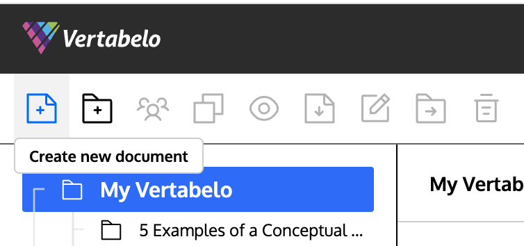
You can draw your logical data model in Vertabelo with these entities. Simply log into the Vertabelo data modeler and click Create new document.
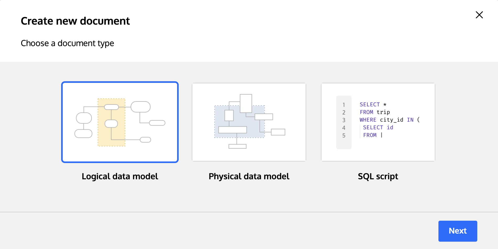
Then select Logical data model and click Next.
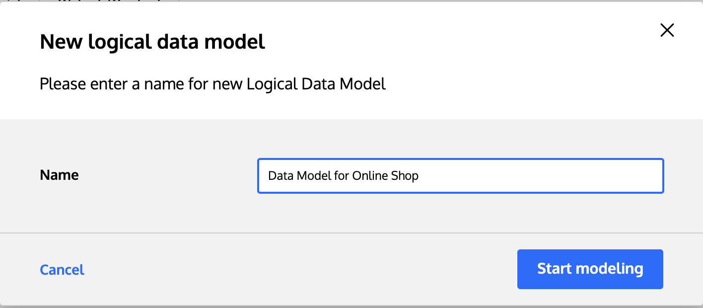
Next, enter a suitable name for your model and click Start modeling.
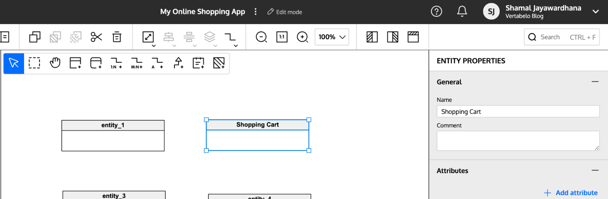
Now you can start drawing your logical data model. You can add new entities by clicking the Add new entity tool and clicking on the diagram area.
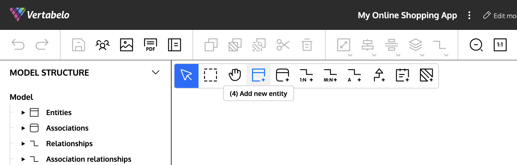
Select the entity and change its properties in the Properties panel on the right-hand side of the screen.
Step 2: Add Attributes and Define Their Data Types
Now it’s time to add attributes to your entities. Attributes are the properties of each entity; they will become the physical database table columns.
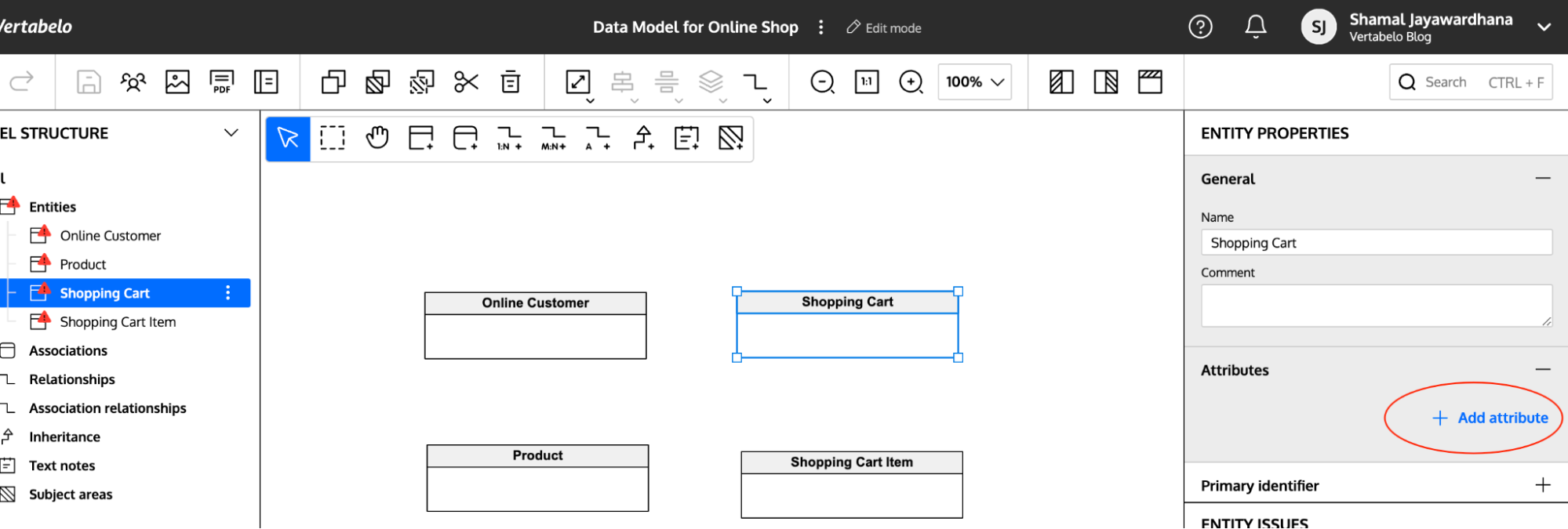
First, list the attributes for each entity. Then, select the entity, choose the Properties panel, and click Add attribute.
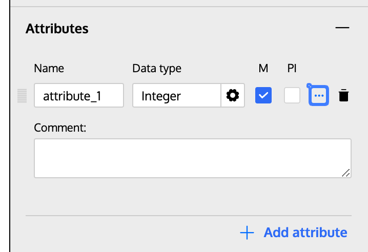
You can enter a name for each attribute and choose the data type from the list. Check M if it’s mandatory. And check PI if the attribute is the primary identifier (primary key) of its table. You can also add comments for each attribute in the Comments field.
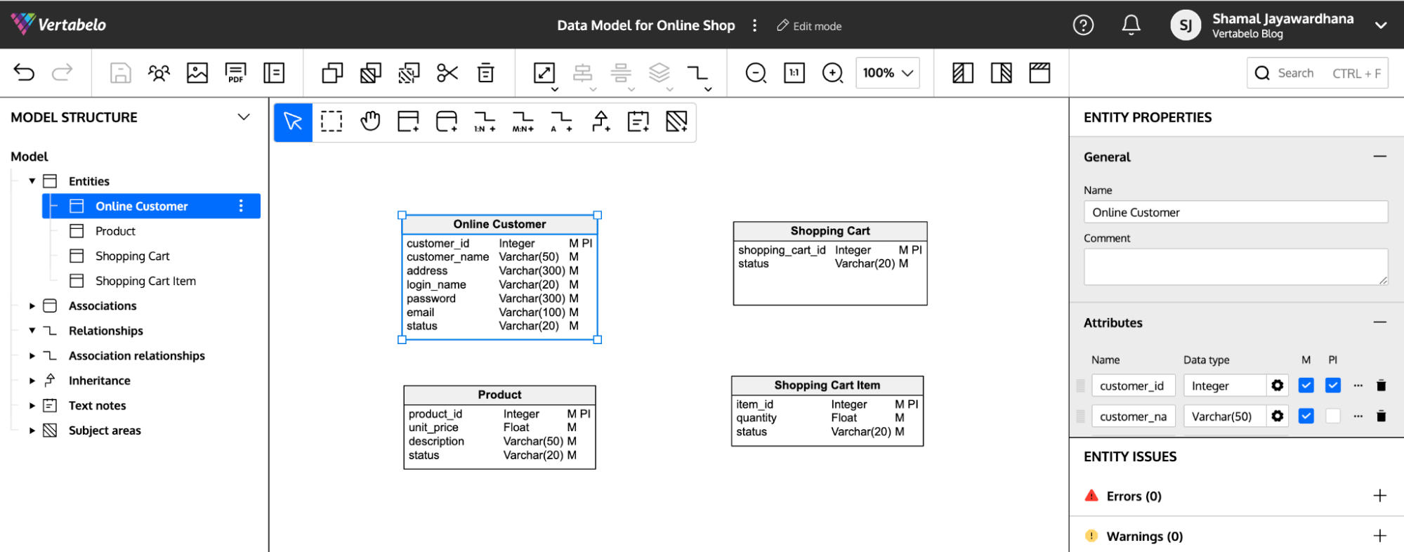
When you’ve added all the attributes with their data types, your model will look something like this:
Step 3: Add Relationships
Next, you’ll add relationships between the entities.
First, decide the relationships between each entity combination in your diagram. For instance, the relationships in our online shopping app data model will be as follows:
- Online Customer and Shopping Cart → One-to-Many (1:N)
- Shopping Cart and Shopping Cart Item → One-to-Many (1:N)
- Product and Shopping Cart Item → One-to-Many (1:N)
Depending on the relationships, you can use the toolbox buttons circled in red to add them between entities:
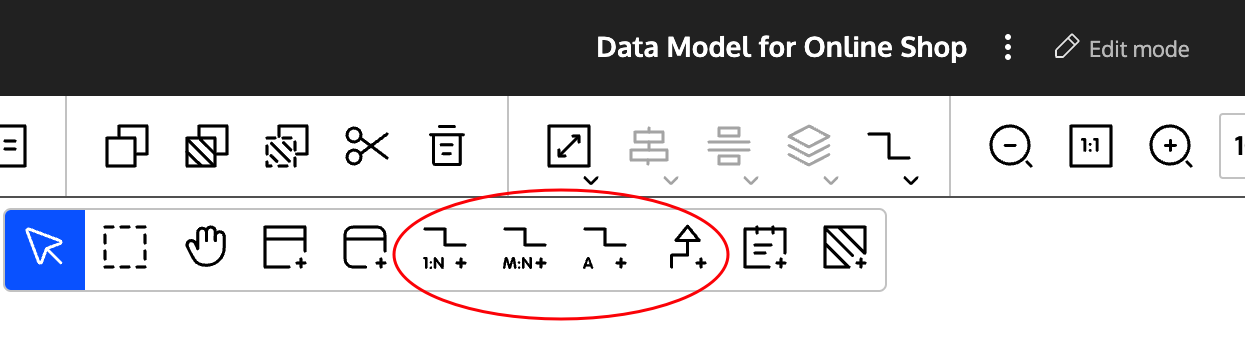
To add a relationship, first click on the appropriate toolbox button. Then click on the first entity and drag and release on the second entity.
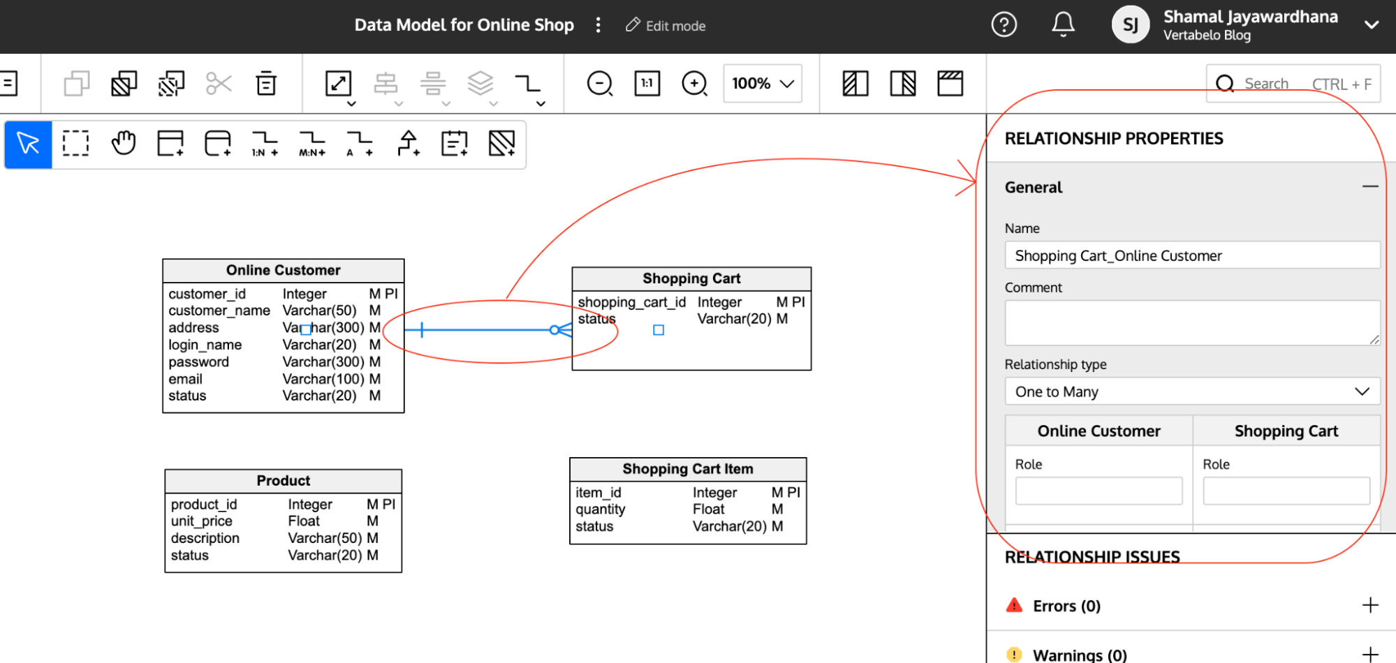
You can change the relationship properties by selecting the relationship and changing the values in the Relationship Properties panel:
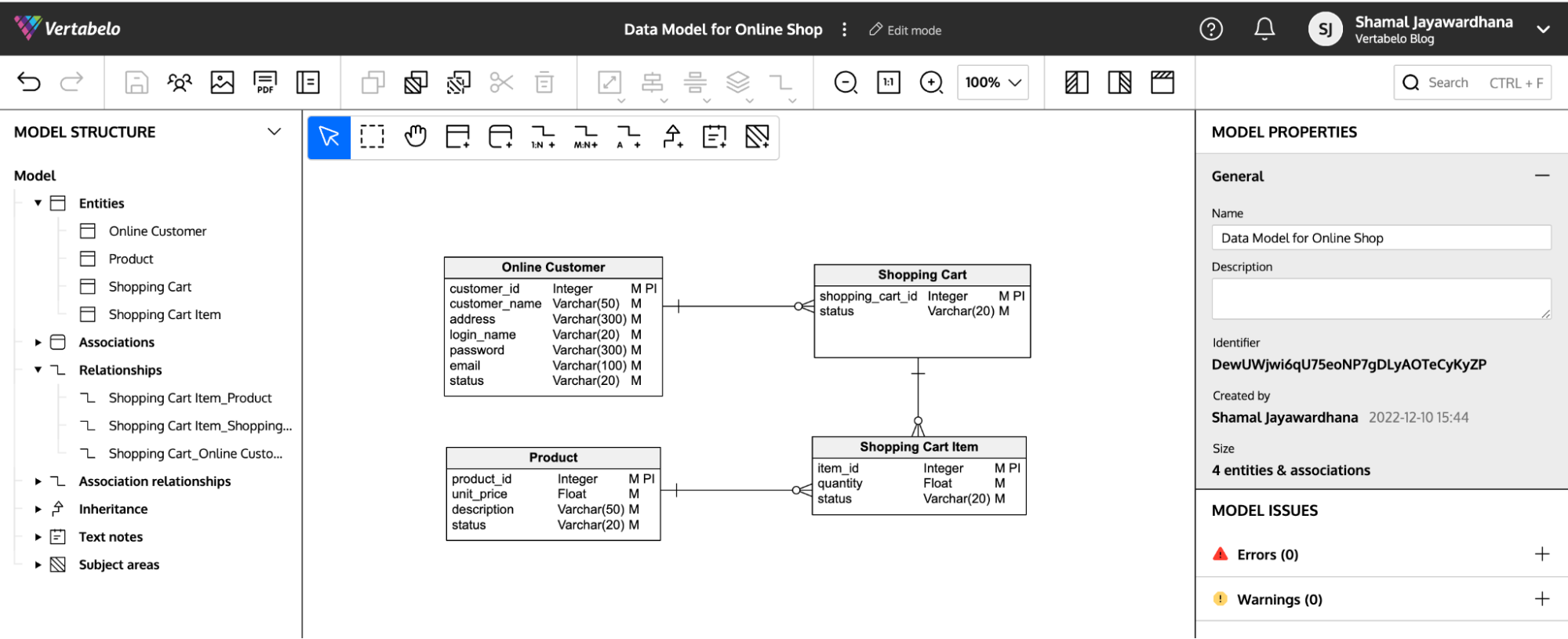
After adding relationships, your logical diagram will look something like this:
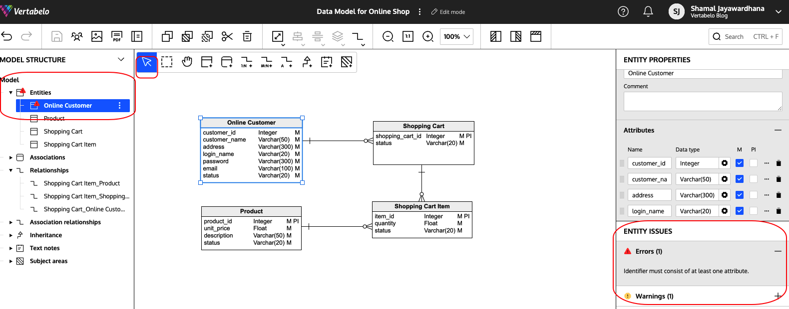
Vertabelo’s model validation feature gives you alerts with errors and warnings so you can be sure you’re on the right track. It highlights entities that have default names, missing attributes, missing primary identifiers, etc.
Step 4: Generate the Physical Model
Now you can create your physical diagram. In Vertabelo, you can convert your logical diagram to a physical model in just a few clicks.
Click on the model name, which opens the main menu. Then click the Generate physical model option. Don’t forget to choose Microsoft SQL Server as the target database engine in the pop-up customization menu.
You can read this article on generating a physical diagram from a logical diagram in Vertabelo for more details.
After generation, your physical data model will appear:
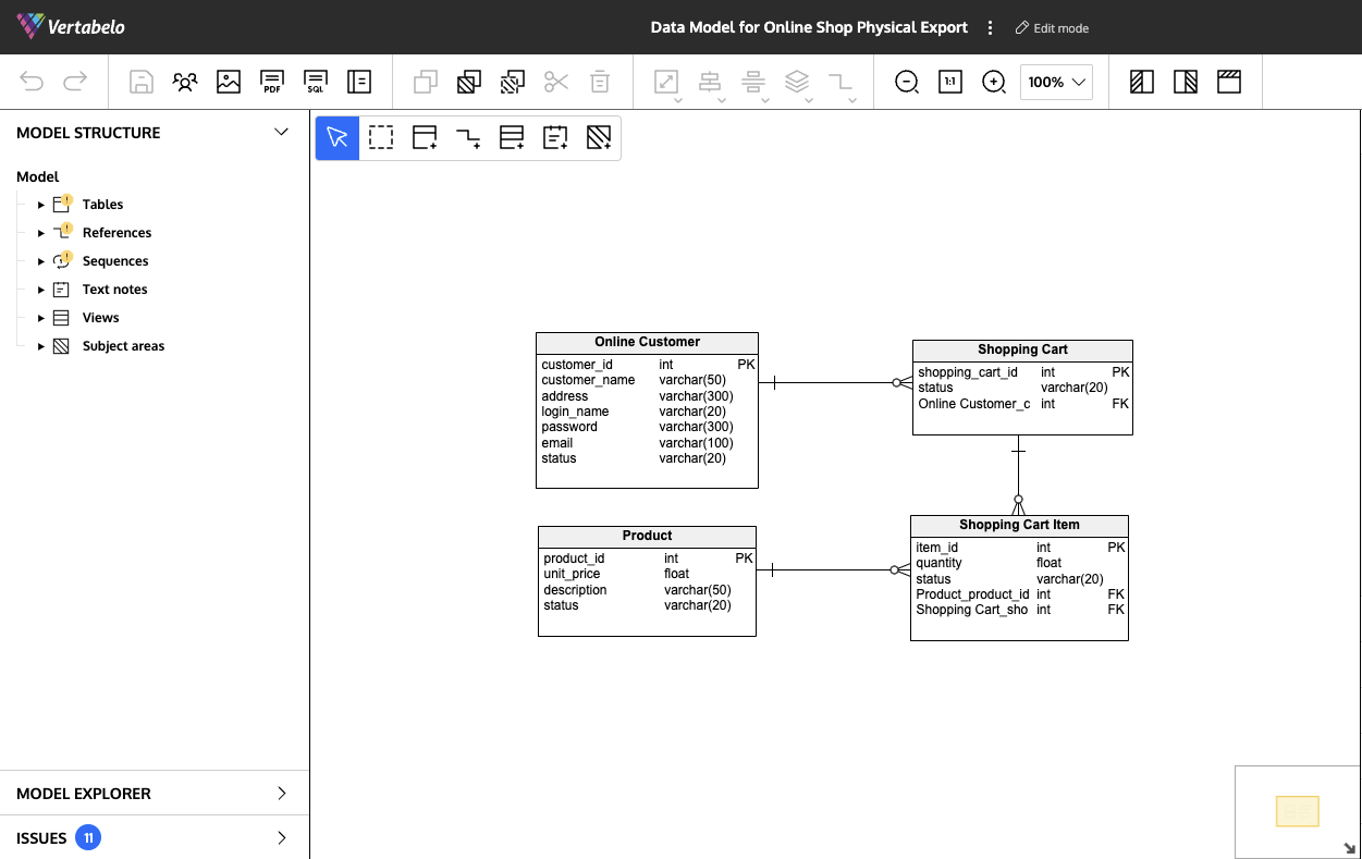
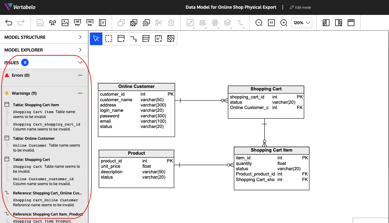
Now you can check the warnings and error messages provided by Vertabelo’s Model Validation feature and fill in the missing details, e.g. defining keys, adding constraints or indexes, etc.
To do this, click on Issues in the navigation tree. You’ll see the error messages and warnings.
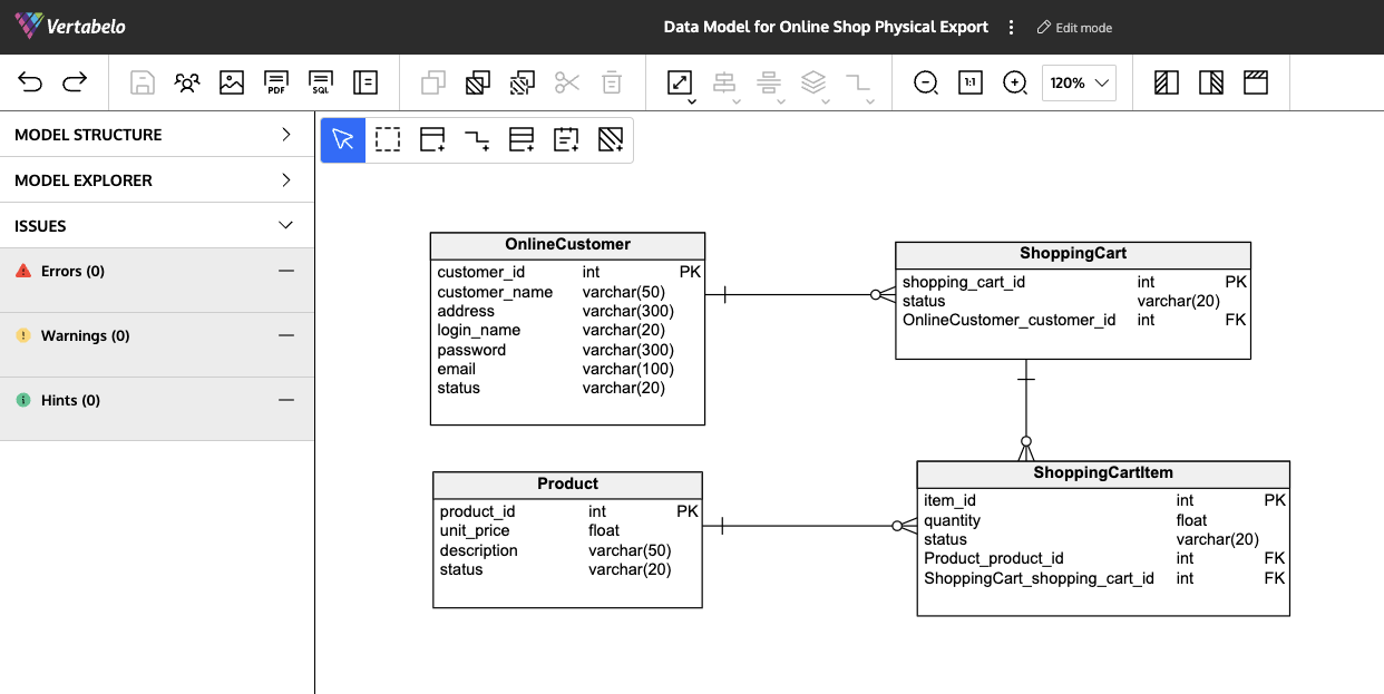
After you make the needed corrections, your physical model should look like this:
Vertabelo offers more features to simplify your database diagram creation in SQL Server. Some popular options include text notes, subject areas, and coloring diagrams.
Congratulations! You have successfully created a database diagram in SQL Server. You can now create your physical database from the physical diagram by using Vertabelo’s automatic DDL script generation feature.
Step 5: Generate a DDL Script
Click on the Generate SQL Script button in the data modeler’s upper panel. You'll see this:
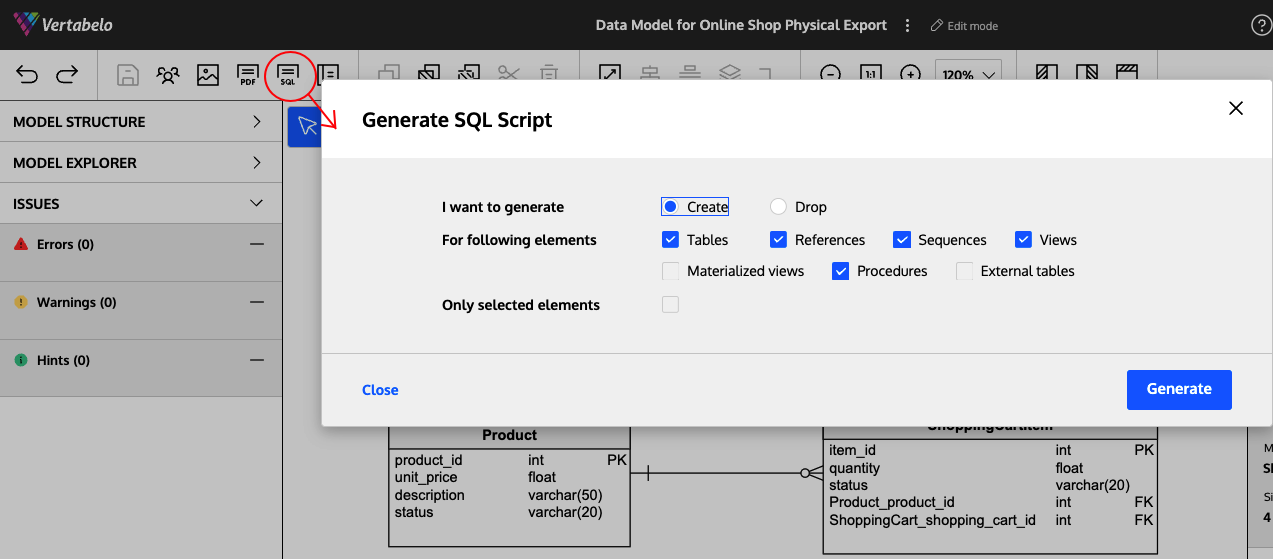
Select your preferences and click Generate.
You can see the generated SQL script as shown below:
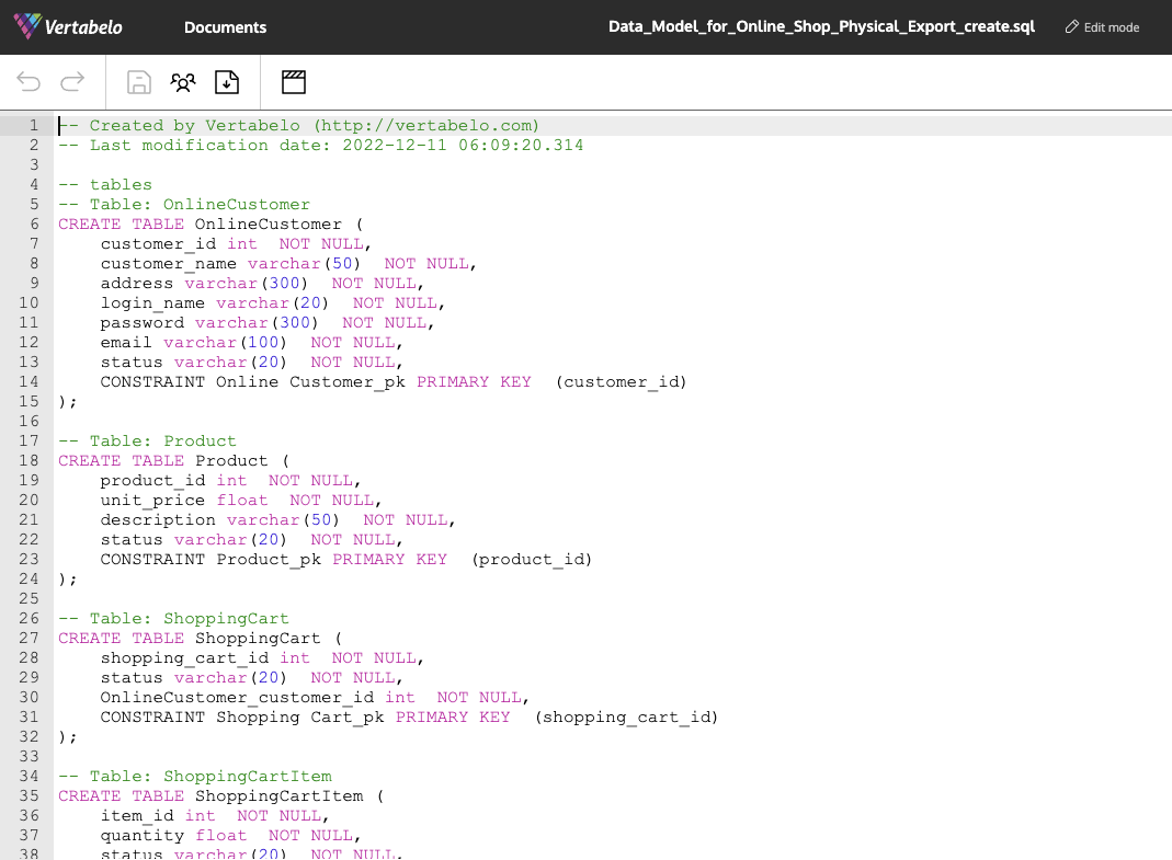
You can read more on how to generate a SQL script in Vertabelo here.
Step 6: Create the Physical Database Structures Using the DDL script
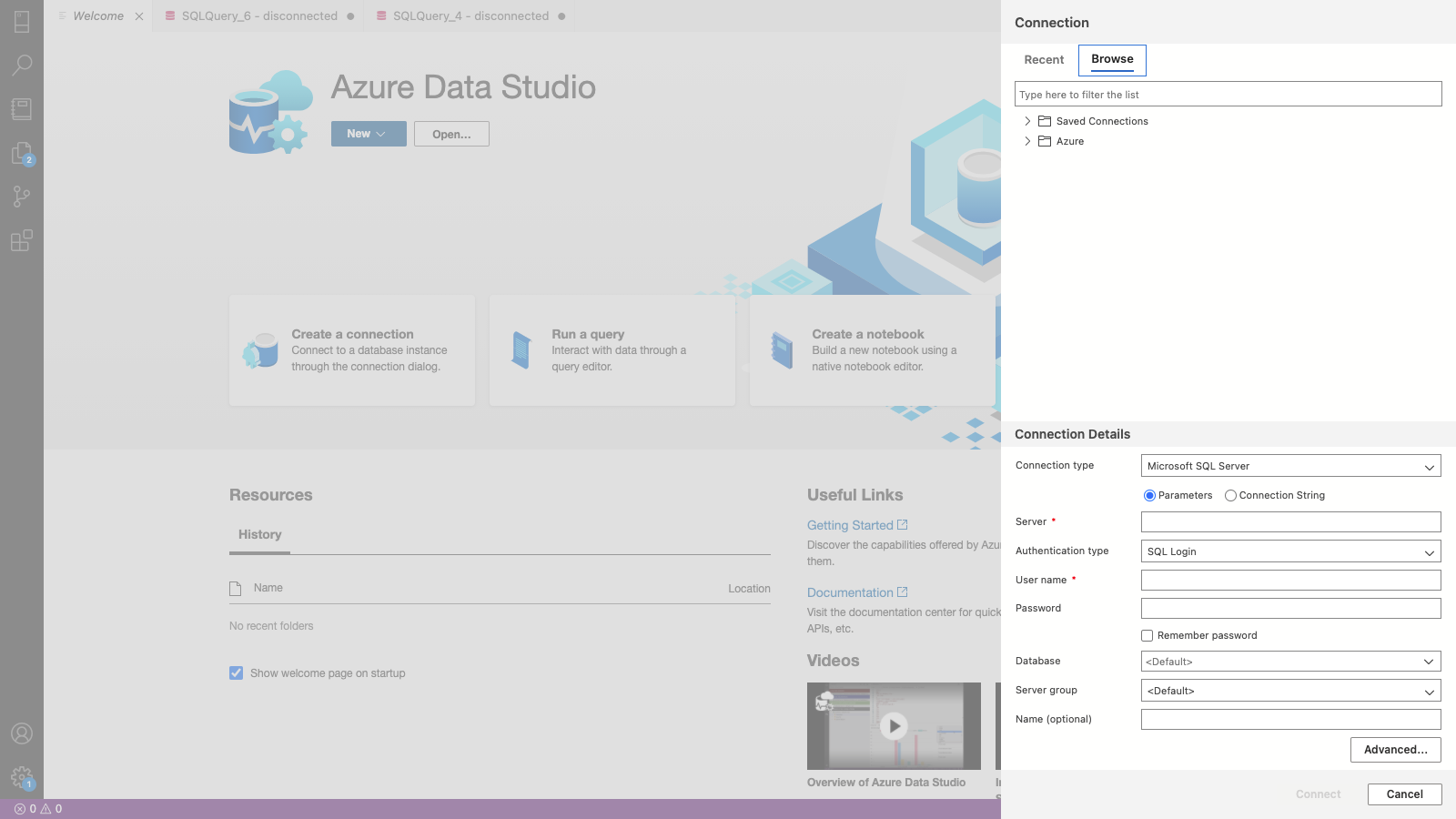
Now you can use the created DDL script to create your physical database structures. I will show you how to do it in Azure Data Studio.
First, create a connection:
Then click New Query in the upper panel:

Then copy and paste the SQL script you generated into the Azure Data Studio query editor. You can correct any errors highlighted in the editor.
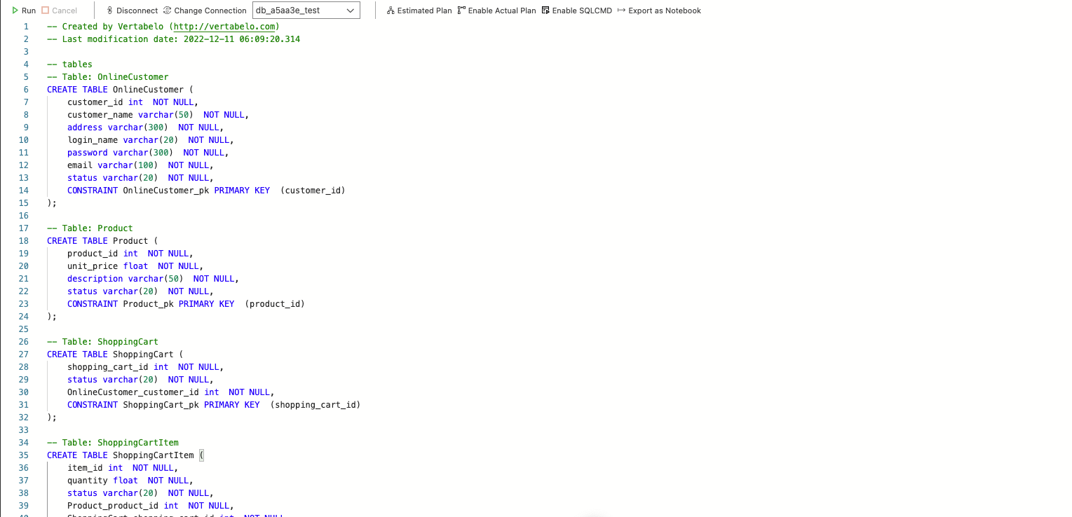
Then click Run in the upper panel.
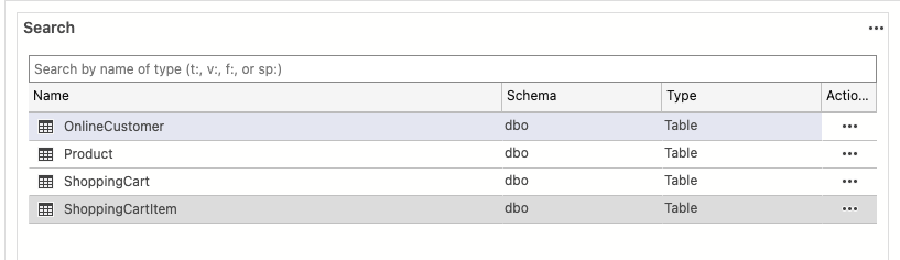
All done! Our physical database for an online shopping app has been created in SQL Server.
A New SQL Server Database Diagram Really Is That Easy!
Creating a database diagram in SQL Server can be done with a few easy steps if you have a data modeling tool like Vertabelo. You can start with the logical diagram and create the physical diagram from it with Vertabelo’s automated options. After finalizing the physical data model, you can create a DDL script using another handy Vertabelo feature. Then simply copy the script and paste it on the query editor of a tool like Azure Data Studio to create the physical database structure in SQL Server. Why not try it for yourself?
